- Page 1
- Page 2
- Page 3
- Page 4
- Page 5
- Page 6
- Page 7
- Page 8
- Page 9
- Page 10
- Page 11
- Page 12
- Page 13
- Page 14
- Page 15
- Page 16
- Page 17
- Page 18
- Page 19
- Page 20
- Page 21
- Page 22
- Page 23
- Page 24
- Page 25
- Page 26
- Page 27
- Page 28
- Page 29
- Page 30
- Page 31
- Page 32
- Page 33
- Page 34
- Page 35
- Page 36
- Page 37
- Page 38
- Page 39
- Page 40
- Page 41
- Page 42
- Page 43
- Page 44
- Page 45
- Page 46
- Page 47
- Page 48
- Page 49
- Page 50
- Page 51
- Page 52
- Page 53
- Page 54
- Page 55
- Page 56
- Page 57
- Page 58
- Page 59
- Page 60
- Page 61
- Page 62
- Page 63
- Page 64
- Flash version
© UniFlip.com
Innovative Storage Solutions
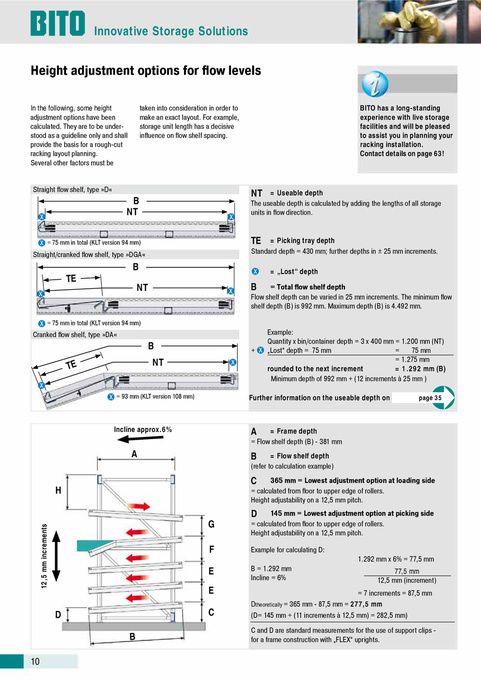
Height adjustment options for flow levels
In the following, some height adjustment options have been calculated. They are to be understood as a guideline only and shall provide the basis for a rough-cut racking layout planning. Several other factors must be Straight flow shelf, type »D«
X
taken into consideration in order to make an exact layout. For example, storage unit length has a decisive influence on flow shelf spacing.
BITO has a long-standing experience with live storage facilities and will be pleased to assist you in planning your racking installation. Contact details on page 63!
B NT
NT
X
= Useable depth The useable depth is calculated by adding the lengths of all storage units in flow direction.
X = 75 mm in total (KLT version 94 mm)
TE
X X
Straight/cranked flow shelf, type »DGA«
= Picking tray depth Standard depth = 430 mm; further depths in ± 25 mm increments. = „Lost“ depth
TE
X
B NT
B
= Total flow shelf depth Flow shelf depth can be varied in 25 mm increments. The minimum flow shelf depth (B) is 992 mm. Maximum depth (B) is 4.492 mm. Example: Quantity x bin/container depth = 3 x 400 mm = 1.200 mm (NT) = 75 mm + X „Lost“ depth = 75 mm = 1.275 mm rounded to the next increment = 1.292 mm (B) Minimum depth of 992 mm + (12 increments à 25 mm )
X = 75 mm in total (KLT version 94 mm)
Cranked flow shelf, type »DA«
B NT
X
TE
X
X = 93 mm (KLT version 108 mm)
Further information on the useable depth on
page 35
Incline approx.6%
A
= Frame depth = Flow shelf depth (B) - 381 mm = Flow shelf depth (refer to calculation example) 365 mm = Lowest adjustment option at loading side = calculated from floor to upper edge of rollers. Height adjustability on a 12,5 mm pitch. 145 mm = Lowest adjustment option at picking side = calculated from floor to upper edge of rollers. Height adjustability on a 12,5 mm pitch. Example for calculating D: 1.292 mm x 6% = 77,5 mm B = 1.292 mm Incline = 6% 77,5 mm 12,5 mm (increment)
A H G F E E D
B
B
C
D
12,5 mm increments
C
= 7 increments = 87,5 mm Dtheoretically = 365 mm - 87,5 mm = 277,5 mm (D= 145 mm + (11 increments à 12,5 mm) = 282,5 mm) C and D are standard measurements for the use of support clips for a frame construction with „FLEX“ uprights.
10