1
N and B controllers
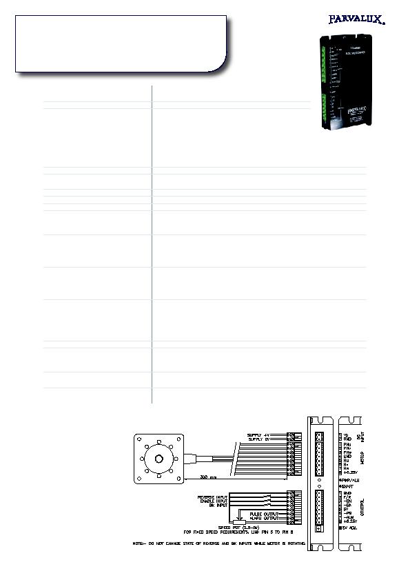
N and B controller wiring example
Controller type
Brushless DC controller
2 quadrant (reversible rotation)
Supply voltage
24 V DC (16-32 V)
Continuous current
PBLCN42-87-24
7. A
PBLCB42-107-24
10 A
PBLCN60-78-24
A
PBLCN60-8-24
7. A
PBLCB60-118-24
10 A
PBLCB60-138-24
1 A
PBLCB86-1-48
10 A
Peak current
2x continuous current
Control method
Closed loop speed control
Block commutation with pulse width modulation (PWM)
Motor feedback
3 Hall sensors, 120 electrical degree spacing
Switching devices
6 MOSFET transistors
Switching frequency
18 kHz
Analogue speed input
Speed input for analogue voltage or potentiometer
Maximum speed is adjusted using SV ADJ. preset on side of controller.
For controllers sold with geared motors, speed is preset during manufacture.
3 digital inputs (switch or TTL)
F/R connect to 0V for reverse (anticlockwise) rotation.
-EN connect to 0V to enable.
-BK connect to 0V to override speed pot and hold motor stationary.
Do not change status of F/R and BK inputs while motor is rotating.
2 digital outputs
(open collector)
-PG Motor speed pulse output. Logic 0 (low) pulses 0.0 ms long
Pulses per rev = 3 * number of poles.
Frequency in Hz = (motor rpm/60) * 3 * number of poles.
-ALM Fault output. Low under fault condition.
2 status LEDs
PWR/ALM Lights when power is connected. Blinks under fault condition
eg peak current reached, supply voltage low, motor not
connected. Blinks for a few seconds after continuous current
exceeded.
SHAFT Lights when shaft is turning
Supply output for control circuits
0V and +6.2V provided for potentiometer etc. Max current 10 mA.
Construction
Aluminium chassis/heat sink, fi nned on B controller
Enclosed construction with pressed steel cover
Slots for mounting screws provided on 2 faces
Connectors
Separate in-line connectors (.08 mm pitch) for power supply, motor and control
Mating connectors are supplied with controller
Weight
N controller
0.37 kg
B controller
0.7 kg