14
S controller
Controller type
Brushless DC controller
2 quadrant (reversible rotation)
Supply voltage
24 V DC (16-32 V)
Continuous current
PBLCS42-47
2. A
PBLCS42-67
A
Peak current
2x continuous current
Control method
Closed loop speed control
Block commutation with pulse width modulation (PWM)
Motor feedback
3 Hall sensors, 120 electrical degree spacing
Switching devices
6 MOSFET transistors
Switching frequency
18 kHz
Analogue speed input
Speed input for analogue voltage or potentiometer.
A 4.7 k potentiometer is supplied.
Maximum speed is preset during manufacture according to order.
For fi xed speed requirements, speed is preset during manufacture.
1 digital input (switch or TTL)
F/R
connect to 0V for reverse (anticlockwise) rotation.
Do not change status of F/R input while motor is rotating.
1 digital output (TTL)
PG
Motor speed pulse output. Logic 1 (high) pulses 0.2 ms long
Pulses per rev = 3 * number of poles.
Frequency in Hz = (motor rpm/60) * 3 * number of poles.
1 status LED
PWR Lights when power is connected
Supply output for control circuits
0V and +V provided for potentiometer etc. Max current 10 mA.
Construction
Aluminium chassis/heat sink
Enclosed construction with pressed steel cover
Slots for mounting screws provided on 2 faces
Connectors
Separate in-line connectors (3. mm pitch) for power supply, motor and control
Mating connectors are supplied with controller
Weight
0.1 kg
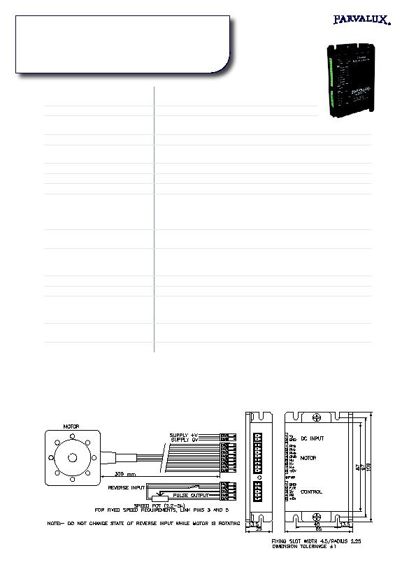
S controller wiring example and outline drawing