WWW.NOLINMILLING.COM · SALES@NOLINMILLING.COM
39
2018
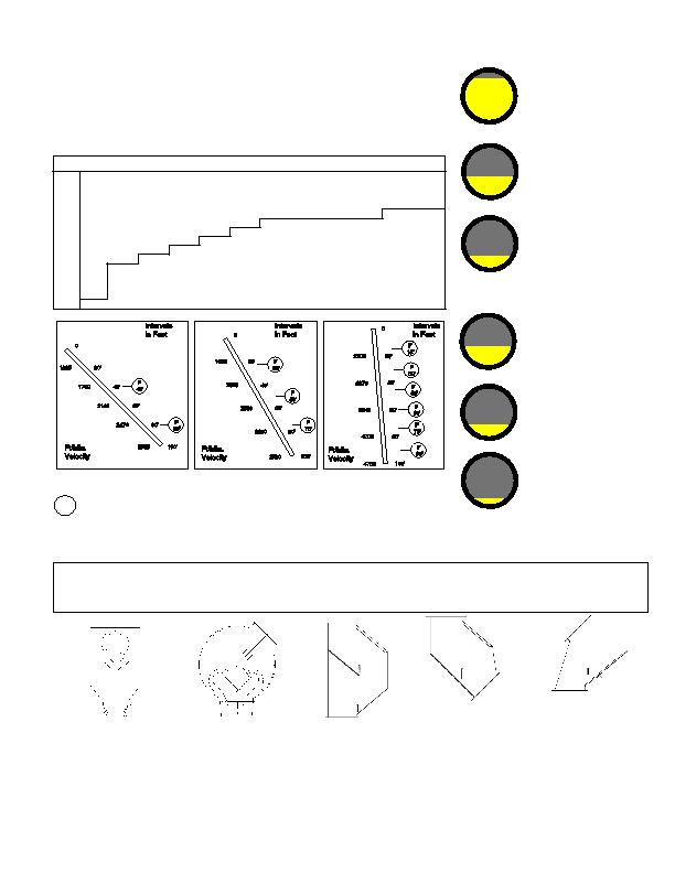
Requires 6 Flow Retarders
Requires 3 Flow Retarders
F
in Feet
90'
75'
60'
45'
30'
15'
75'
50'
25'
80'
= Recommended Location of Inline Flow Retarder as Measured from the Beginning of the Spout
Requires 2 Flow Retarders
Velocity
in Feet
4700
100'
80'
4200
3640
60'
40'
2970
2100
20'
Velocity
3720
3330
2880
2355
1665
100'
80'
60'
40'
20'
40'
Velocity
2765
2470
2140
1750
1235
100'
80'
60'
40'
20'
0
0
0
GRAIN DAMAGE PREVENTION CHART
Research on grain damage versus velocity indicates that every effort should be made to curtail velocities
of over 1750 FPM (feet per minute). The bold line indicates the point at which one should view the condition
as critical and take appropriate steps to reduce the velocity. Flow Retarders, Dead Stops, and Adjustable
Spout Ends help preserve grain quality and extend equipment life. Spout systems need to run at or near
capacity to maintain grain quality and prevent premature equipment wear.
The following table indicates approximate velocities that will be attained by whole dry grains flowing freely
in smooth metal spouts of various lengths and of various angles in relation to the horizontal. This chart
DOES NOT apply to grain with high moisture percentages.
At 400 feet per minute off
a bucket elevator - spout
is nearly full.
At 800 feet per minute
spout is approximately
half full.
At 1600 feet per minute
spout is approximately
one fourth full.
VELOCITY IN FEET PER MINUTE
Spout
Length
35°
40°
45°
50°
55°
60°
65°
70°
75°
80°
85°
90°
5'
400
524
618
700
770
830
885
935
975
1010
1050
1075
10'
570
742
875
990
1090
1180
1255
1320
1380
1435
1485
1520
15'
696
908
1070
1210
1335
1440
1530
1615
1690
1755
1820
1860
20'
805
1047
1235
1400
1540
1665
1770
1870
1950
2025
2100
2150
25'
899
1170
1380
1560
1725
1860
1975
2085
2180
2265
2340
2400
30'
985
1280
1520
1710
1890
2040
2165
2285
2390
2480
2570
2635
40'
1135
1480
1750
1975
2180
2355
2500
2640
2760
2865
2970
3040
50'
1270
1655
1950
2210
2440
2635
2800
2955
3090
3210
3320
3400
60'
1390
1810
2140
2420
2670
2880
3065
3240
3390
3520
3640
3720
70'
1500
1960
2310
2615
2880
3110
3315
3500
3660
3800
3930
4025
80'
1605
2090
2470
2795
3080
3330
3540
3740
3905
4055
4200
4295
90'
1705
2220
2620
2960
3275
3535
3760
3965
4150
4310
4460
4550
100'
1795
2340
2765
3120
3450
3720
3960
4180
4370
4540
4700
4800
In a spout with no flow retarders, the lower end of the spout will wear out first due to the increased velocity
of the grain and concentrated contact area. A flow retarder reduces the velocity by forming a moving pile on
the baffle. The incoming grain is de-accelerated by contact with the moving pile.
It is important that the entire grain handling system be designed to have spouts run near rated capacities
at
all times. Additional flow retarders may be required for some products. Spouts not run at full
capacities
may need additional flow retarders.
At 1600 feet per minute,
spout is approximately
one eighth full.
At 800 feet per minute,
spout is approximately
one fourth full.
At 400 feet per minute
from a bucket elevator but
at the spout's half rated
capacity, the spout is
approximately half full.
FLOW RETARDER
WITH STANDARD FLANGES
Use this in situations where you
would normally flange spout. "V"
baffle allows for full flow of material.
Baffle will create moving pile in all
situations except when trickling a
low volume of grain. Flowing into a
moving pile is important to maintain
material quality and prevent premature
wear.
Specifications page 45
ADJUSTABLE SPOUT END,
ORIGINAL STYLE
"V" baffle allows for full flow of material.
Grain entering at various angles is
cushioned into a moving pile of grain.
Baffle will create moving pile in all
situations except when trickling a
low volume of grain. Flowing into a
moving pile is important to maintain
material quality and prevent premature
wear.
Specifications page 45
Square in and square out with 1/4"
black rubber cushion on back end
plate at approximately 40°. Baffle is
located below the angle of projection
allowing a pile to form on rubber
cushion. Rubber on back end plate
cushions and slows material flow,
thus forming pile. Unique back
sweep design as shown on drawing.
Better for varied flow rates. 7 gauge
carbon steel construction.
Specifications page 46
VERTICLE DROP
FLOW RETARDER
Special baffle design creates a
moving pile at most flow rates,
thus retarding material speed.
Units should be installed on ten
foot intervals. 7 gauge carbon
steel construction, 1/2" baffles,
7 gauge AR steel on wear
points. For round spouts use
inlet and square to round.
Specifications page 46
Used when a spout comes
straight down. Unit turns out 45°
and has 1/2" thick internal baffle
to reduce grain velocity and form
a moving pile at point of impact. 7
gauge carbon steel construction,
1/2" baffle, 7 gauge AR steel
liner on bottom. Square in and
square out. For round spouts,
use inlet and square to round.
Specifications page 46
STARTING FULL
STARTING HALF FULL
45° Spout - 100' Long
Requires 2 Flow Retarders
60° Spout - 100' Long
Requires 3 Flow Retarders
85° Spout - 100' Long
Requires 6 Flow Retarders
= Recommended Location of Inline Flow Retarder as Measured from the Beginning of the Spout
F
Z 45° SQUARE
DEAD STOP WITH
RUBBER CUSHION
VERTICLE DROP
CUSHION TURNOUT
45° ELBOW
in Feet