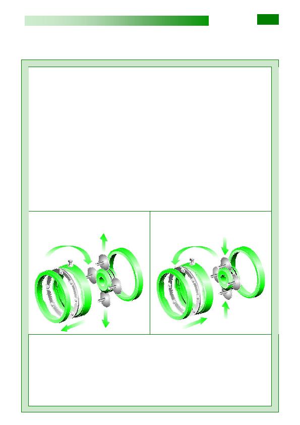
bero motore e la pista 11 pressata dalle
molle a tazza 12 trasmettono la rotazione
ai satelliti 7 i quali, traslando sulle due pi-
ste esterne 6 e 9, pongono in rotazione il
porta satelliti 2 (solidale all'albero di usci-
ta) al quale sono collegati tramite le boc-
cole scorrevoli 3.
rotazione della pista 6 con relativo sposta-
mento assiale della stessa; tale sposta-
mento è dovuto all'azione delle sfere 5
sulle piste delle due camme contrapposte
4 e 6 ed agisce sui fianchi conici dei satel-
liti, i quali si spostano radialmente all'in-
terno delle piste 10 e 11, vincendo la rea-
zione delle molle 12. In questo modo, al
variare della posizione del contatto sui
fianchi dei satelliti, si determina la varia-
zione della velocità del porta satelliti e
quindi dell'albero uscita.
mai essere effettuata a variatore fermo.
nella descrizione del principio di funziona-
mento sono elencati a pagina 10.
shaft and the mobile one 11 pressed by
the Belleville washers 12, transmit the ro-
tation to planetary discs 7 that moving on
the two outer races 6 and 9, rotate accord-
ingly the planetary disc holder 2 - one
piece with the output shaft - to which the
planetary discs are connected through the
sliding bushes 3.
The hand wheel controls the rotation of
the race 6 and its axial movement.
Such shifting is owed to the action of balls
5 on the two opposed cams 4 and 6, and it
acts on the cone sides moving them ra-
dially inside the races 10 and 11 winning
this way the reaction of the springs 12.
The variation of contact position on plane-
tary discs originates the speed variation of
planetary disc holder and accordingly of
output shaft.
the variator is at standstill.
Items of internal parts used in working
principle description are listed at page 10.
Motorwelle verbunden ist, und die Lauf-
bahn 11, die von den Tellerfedern 12 ge-
presst wird, übertragen die Drehung an
den Satelitten 7 die dann auf den zwei
Aussenbahnen 6 und 9 laufen und den
Satelittenträger in Rotation zwingen, (die-
ser ist mit der Ausgangswelle fest verbun-
den) und die Satelliten sind am Satelli-
tenträger mittels Gleitbuchsen befestigt.
Mit der Drehung des Steuerrades bewirkt
man die Rotation der Laufbahn 6 und
dessen axialen Verschiebung; diese Ver-
schiebung wird von den Kugeln 5 auf der
Laufbahn der zwei gegenüberliegenden
Stuerkurven 4 und 6 ermöglicht und wirkt
auf die konischen Seitenflächen der Satel-
liten die sich entgegen der Federkraft 12
durchsetzten und radial hinein in den
Laufbahnen 10 und 11 bewegen. In dieser
Weise, beim Verstellen der Position der
Kontaktfläche auf der Satellitenseite, wird
die Geschwindigkeit des Satellitenträger
und somit der Ausgangswelle bestimmt.
nie bei stehendem Verstellgetriebe er-
folgen.
onsprizip beschrieben, sind auf Seite 10
dargestellt.
I motori elettrici sono forniti con voltaggio
trifase 230/400V (±10%) e monofase
230V, frequenza 50Hz, 4 poli, classe di
isolamento F con temperatura ambiente di
40°C, grado di protezione IP 55.
A richiesta, motori con caratteristiche di-
verse, monofasi ad alta coppia di spunto,
autofrenanti, a doppia polarità.
La morsettiera è posta come standard dal
lato volantino di comando (v. pag. 4).
The electric motors are supplied with volt-
age 230/400V (±10%) three-phase and
230V single-phase, frequency 50 Hz, 4
poles, temperature class F at ambient
temperature 40 Celsius, protection IP55.
On request, motors according to different
specifications, high starting torque single-
phase, brake-motors, dual-speed motors.
The terminal box is located as standard on
the same hand wheel side (see page 4).
Als Elektromotoren kommen Dreiphasen-
motoren mit 230/400 V (+/- 10%) und Ein-
phasenmotoren mit 230 V, 50 Hz, 4-polig,
Isolationsklasse F bei 40°C Umgebungs-
temperatur in Schutzart IP 55 zum Ein-
satz. Auf Anfrage sind auch Motoren in
Sonderausführungen lieferbar, ebenso wie
Bremsmotoren, Einphasenmotoren mit ho-
hem Anlaufmoment, polumschaltbare Mo-
toren. Als Standard befindet sich der
Klemmkasten auf der selben Seite des
Steuerrades (siehe Seite 4)