background image
KG
General Information and Maintenance Instructions
Construction
The frame comprises pressure die-castings accurately located
together, alternatively on machined spigots of the hydraulically riveted stator
packs, ensuring concentric air gap with correct bearing alignment. The armature
laminations or die-cast rotor are pressed onto a precision steel shaft. The
armature after winding, impregnation and baking is then statically and dynamically
balanced. All stators and armatures are wound with first class quality synthetic
covered copper wire manufactured to B.S. Specification 2757 ( IEC 85) Class "F"
and then impregnated and baked in our Automatic Plant, and accordingly can be
considered to be tropically impregnated for all practical purposes.
Motor Enclosures
To IEC 34-5 and EN 60034:part 5 and IEC 34-6 and
B.S. EN 60034-6. Induction type motors: Our standard ventilated internal fan
cooled frame conforms to IP 20. Commutator type motors SD 1 ventilated
internal fan cooled frame conforms to IP 20. SD 11, SD 12 and PM 1, PM 2
,
PM 6
,
PM 60 Drip Proof enclosure, internal fan cooled, conforms to IP 21. Plain
totally enclosed frame conforms to IP 54. TEFC frames with terminal box
conforms to IP 54.
PM 3, PM 4, PM 5, PM 50, PM 7, PM 8, PM 9, PM 10, PM 11 also conforms to
IP 54.
Bearings
Shielded ball bearings throughout, spring loaded for quiet running.
Temperature parameters -30°C to +100°C/120°C.
Brush Gear
(Commutator motors). An adjustable rocker type for maximum
brush life and good commutation with easily accessible brushes. To achieve
maximum brush life a form factor on the supply voltage as near to 1 as possible
would be required.
Testing
To B.S. Specification 5000 Part II. ( IEC 72). All our units are CE
marked and comply to current regulations/directives at time of printing.
Torque Ratings
All gearbox torque figures have been reproduced to represent
an accurate output figure. These figures may be affected by tolerances created
during production techniques as well as application circumstances once the units
have been installed. A margin of + or ­ 10% should be taken into
consideration on these figures during your selection of an appropriate unit.
Temperature
All motors are built with Class "F" insulation to B.S. 2757
( IEC 85) which allows a temperature rise of 115°C based on an ambient of
40°C. These figures are with the motor running in normal working conditions in
free air and not in any form of enclosure. Under full load the heat of the motor
casing will be such that it is NOT possible to handle for any length of time.
Braking
The problem of instantaneously stopping a motor or geared unit can
be overcome by fitting an electromagnetic brake, details on pages 6, 45 and 72.
Gear units
The motor is fitted with shielded spring loaded ball bearings
absorbing worm thrust from the gear box. The output shaft with flats or keyways
is carried in ball bearings pressed into gear wheels of composite or phosphor
bronze with hardened and polished steel worms. Gearbox and ball bearings
packed with appropriate grade of grease. Worm and multi-spur gear units are
fitted with case hardened steel spur gears with an oil bath lubrication. All units
are suitable for running in any position.
Gearbox positions
Alternative positions for the gearboxes can be arranged to
suit customer's requirements (see page 113) but unless specified, will be
supplied in standard position as shown on the individual drawings. This also
applies to the gearbox shaft extensions.
Lubricants
Single and double reduction worm gearboxes are charged with a
suitable semi-fluid grease and sealed for life. Worm and multi-spur and in-line
spur gearboxes are filled with 20/50 multigrade oil and sealed for life, (in certain
conditions semi-fluid grease may be used). Working temperature of lubricants:-
Grease -15°C to 120°C; Oil -15°C to 150°C. For units used in extreme
temperature conditions i.e., below zero degrees centigrade please contact our
sales department.
Single and double worm reduction gearboxes
Whilst worm gearing has
lower efficiency than spur gearing it is true to say that generally the noise level of
worm gear reduction is much lower and therefore, where noise is an important
factor, this type of gearing should be considered. To prevent premature gear
failure or excessive gear wear, the maximum gear loading and thermal rating of
the particular gearbox must be taken into consideration otherwise there is a
danger of stripping the gear wheel teeth or failure of the lubrication due to
excessive gearbox temperature. If further information is required on this point
please consult our sales engineers. The table below shows the recommended
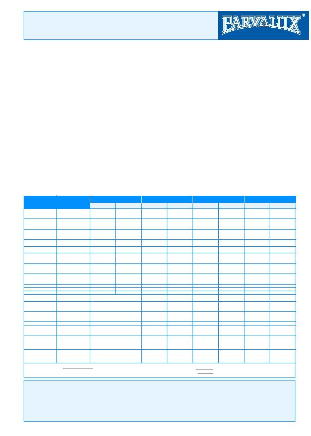
mechanical and thermal ratings for the various types of gearbox.
Maintenance Instructions
All units are fitted with grease packed shielded ball bearings and sealed for life, this can vary depending on operating conditions, temperature, and duty cycle. We recommend replacing
a noisy bearing, as re-greasing is not possible. Prolonged storage can shorten the estimated life (in excess of 20,000 hours).
In most cases dismantling of the motor or gearbox is straightforward. Carefully note the position of spring loaded washers, shims, etc. However the commutator type motors require a
suitable extractor to remove the armature from the main frame. Commutator motors require more maintenance than induction type due to the accumulation of carbon dust in the brush
gear area. This dust should be blown out periodically with a dry air supply observing Health & Safety. Directives regarding inhalation of carbon dust and only when the commutator
surface is in a very blackened condition should it be lightly cleaned with `flour' paper or similar (note not emery paper). When replacing carbon brushes (which may have a life of some
2000 hours depending on operating conditions) care should be taken to ensure these are a free fit in the brush holders. When dismantling, the brush gear should be marked to ensure it
is replaced in the original position and the pigtails clear the motor casing. Magnetic brakes require little maintenance since wear of the bonded lining is automatically compensated for.
COMPOSITE
COMPOSITE
LBS
LBS
BRONZE
BRONZE
KG
Gearbox
Type
Ratios
Mechanical Rating (Nm)
Thermal Rating (watts)
*Radial Loading
Axial Loading
4 1/8:1 to 40:1
44:1 to 60:1
66:1 to 70:1
4 1/8:1 to 40:1
44:1 to 60:1
66:1 to 72:1
4 1/8:1 to 40:1
44:1 to 60:1
66:1 to 72:1
5:1 to 40:1
50:1 to 60:1
5:1 to 40:1
50:1 to 60:1
47:1 to 2880:1
3000:1 to 4300:1
4320:1 to 4900:1
47:1 to 2880:1
3000:1 to 4300:1
4320:1 to 5184:1
47:1 to 2880:1
3000:1 to 4300:1
4320:1 to 5184:1
All Ratios
All Ratios
All Ratios
22:1 to 29:1
53:1 to 303:1
64:1 to 18.5:1
15:1 to 43:1
35:1 to 101:1
6:1 to 18:1
24:1 to 72:1
112:1 to 336:1
42:1 to 1461:1
26:1 to 54:1
62:1 to 125:1
145:1 to 1406:1
24 3/4:1 to 98:1
99:1 to 492:1
231:1 to 1680:1
445:1 to 7776:1
45:1 to 136:1
258:1 to 154:1
351:1 to 1539:1
564:1 to 3300:1
S
M
MB or MF
L or LH
LB or LF-LHB
SS
MM
MBM
SIW
MIW
LIW
SIS
MIS
LIS
SWS
MWS
LWS
GWS
2.9
2.3
1.5
7.9
5.9
5.1
7.9
5.9
5.1
14.6
11.3
14.6
11.3
4
2.7
1.5
9
5.9
5.1
9
5.9
5.1
7
17
28
4.5
4
2.5
11.8
7.9
7.3
11.8
7.9
7.3
22
17
22
17
5.9
4
2.5
11.8
7.9
7.3
11.8
7.9
7.3
11.3
28
45
5.7
7.9
12
28
45
23
51
74
11
9
22
45
32
62
100
100
40
90
150
250
20
38
40
60
60
25
45
47
28
50
­
­
­
­
­
­
­
25
45
48
72
72
30
54
58
38
65
­
­
­
­
­
­
­
15
30
50
40
70
12
20
40
20
60
72
20
48
60
40
80
100
150
7
13.5
23
18
32
5.5
9
18
8
27
36
9
22
27
18
36
45.5
68
8
20
24
30
35
8
20
24
12
30
45
10
32
40
25
40
50
80
3.6
9
11
13.5
16
3.6
9
11
5
13.5
20
4.5
14
18
11.4
18
23
36
Approx Thermal Rating (W) =
Final RPM
×
Torque (Nm)
×
(1/n -1) (
=Gear efficiency)
9.55
100%
For intermittent duty the thermal rating for the gearbox is increased by multiplying the appropriate gearbox thermal rating by the factor X =
Duty Cycle%
*Based on midway point of standard shaft extension
(1Nm=10.2cm kp) (1Nm=8.85lbs. ins)
5