DIMENSIONS
TYPE
Isolate and
Insulate Leads
Individually
Isolate and
Insulate Leads
Individually
Reverse Rotation
Reverse Rotation
Join and
Insulate
Join and
Insulate
Reverse Rotation
Reverse Rotation
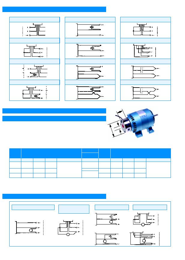
Connection Diagrams for Induction Motors
P1
P3
P5
DIMENSIONS
APPROVALS
TYPE
P2
P4
P6
Brake
Size
P1-P3-P5
Weight
575g
Brake
Size
P2-P4-P6
Recommended Motor Frames
SD 21, SD 41, SD 8 and SD 28
Recommended Motor Frames
SD 13, SD 18 and SD 48
Input
Power
Input
Volts
Rated
Torque
110v
A.C.
0.4
Nm
230v
A.C.
0.4
Nm
24v
D.C.
0.4
Nm
ENCLOSURE
IP 55
Input
Volts
Rated
Torque
110v
A.C.
1
Nm
230v
A.C.
1
Nm
24v
D.C.
1
Nm
24
VA
(14w)
24
VA
(14w)
24
VA
(14w)
A
B
C
35
65
12
All dimensions in (mm)
A: inc. adaptor plate
C.S.A.C-US
C.E. Rec.
"Class F"
Input
Power
24
VA
(14w)
24
VA
(14w)
24
VA
(14w)
A
B
C
35
65
12
All dimensions in (mm)
A: inc. adaptor plate
6
5
17
Two Speed 3 Phase High Speed
Low Speed
Two Speed 1 Phase High Speed
Low Speed
3 Lead Capacitor
Reverse Rotation
4 Lead Capacitor
Reverse Rotation
3 Phase Dual Voltage High Range
Low Range
*Capacitor Start Induction Run
Reverse Rotation
Parvalux Electro Magnetic (Fail Safe) Stop Brakes
(P1-P6) for Induction Motors
Note: Brakes cannot be fitted to T.E.F.C. units.
For frequent stop/starts (more than 3 per minute) please contact our sales engineers.
2 core cable
40cm long
minimum.
B
C
These single-disc electro magnetic brakes are spring applied electrically released units which provide fail to safe operating characteristics, such that on interruption, or failure
of power supply, the brake will engage and arrest the load. These brakes operate from single phase a.c. supply (not P5 or P6) and incorporate a built in rectifier. This offers
the brake a vibration free characteristic through a lower operating voltage spectrum.
}
}
L1
L1
L3
L2
L2
L3
White
Capacitor
White
Black
White
Capacitor
White
Black
White
Red
Red
White
White
Red
Red
White
White
Capacitor
Red
Red
White
White
White
White
White
White
White
White
White
N
N
L
L
N
N
L
L
Red
Yellow
White
Red
Yellow
Capacitor
Red
Yellow
White
Red
Yellow
White
Black
Brown
Blue
Black
Blue
Brown
Black
Blue
Brown
Black
Blue
Brown
Capacitor
15
16
10
A.C. Supply
Reverse Rotation
A.C. Supply
Reverse Rotation
A.C. Supply
A.C. Supply
A.C. Supply
A.C. Supply
Join and
Insulate
*Capacitor start
induction run
units, capacitor
must be
connected in
series with red
lead as shown.
}
}
L1
L1
L2
L3
L3
L2
L1
L1
L2
L3
L3
L2
L1
L1
L2
L3
L3
L2
L
N
L
N
L
N
L
N
L
N
L
N
White
Red
Red
White
A Red
A White
B Red
B White
C Red
C White
B
A
C
B
A
C
White
CAPACITOR
White
Black
White
White
BRAKE
A.C. Supply
L
N
White
White
Black
White
White
BRAKE
A.C. Supply
L
N
Reverse Rotation
L1
L1
L2
L3
L3
L2
HIGH RANGE
A
A
B
B
C
C
BRAKE
Reverse Rotation
L1
L1
L2
L3
L3
L2
LOW RANGE
B
A
C
B
BRAKE
C1
A
Electro-Magnetic Brake Wiring Diagrams
110-250V Three Phase Induction
380-440 Three Phase
(6 lead) Induction
Three Phase Dual Voltage
Three Lead Capacitor
Reverse Rotation
B4
B7
B1
B8
L1
L1
L2
L3
L3
L2
White
White
White
BRAKE
Reverse Rotation
L1
L1
L2
L3
L3
L2
A
A
B
B
C
C
BRAKE
White
Reverse Rotation
}
Capacitor
Capacitor
Capacitor
Capacitor
A
6