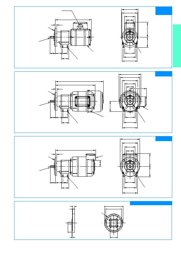
Ø 81
78
45
60
74
50
Ø 51
Ø 35
36
25.5
35.5
23
6.35
SD 21 SIS = 163
SD 41 SIS = 175
73
63
30
193
Ø 96
78
45
60
74
50
Ø 51
Ø 35
36
25.5
35.5
23
6.35
193
Ø 96
78
45
60
74
50
Ø 51
Ø 35
36
25.5
35.5
23
6.35
233 (T.E.F.C.)
Ø 107
80
SD 21 SIS
SD 41 SIS
SD 38 SIS
SD 8 SIS
4
18
1.8
9.5
Ø 35
Ø 88
Ø 75
4 equally spaced holes on 77.2mm
P.C.D. cored 4.1mm dia.
SIS standard
shaft extension
Optional Plastic Mounting Flange
Dimensions in mm. Scale 1:4
NB: Unit drawn is SD 41 SIS
Dimensions in mm. Scale 1:4
Dimensions in mm. Scale 1:4
Dimensions in mm. Scale 1:4
Optional shaft at motor speed (lead end only) 7.93mm dia.
33mm long.
Optional shaft at motor speed (terminal box end only) see separate motor drawing for details (Page 9).
Optional shaft at motor speed (lead end only) see separate motor drawing for detail (Page 9). Not applicable to T.E.F.C. units.
Approx. weight: SD 21 SIS 2.46 Kg
SD 41 SIS 3.02 Kg
Approx. weight: SD 38 SIS 3.77 Kg
Approx. weight: SD 8 SIS 3.72 Kg
Leads out here 30cm
4 holes tapped
M4
9mm deep.
4 holes tapped
M4
9mm deep.
4 holes on 41.27mm P.C.D.
Can be tapped M5
8mm deep.
Tapped 20mm conduit
or PG 13.5 on request.
4 holes on 41.27mm P.C.D.
Can be tapped M5
8mm deep.
4 holes on 41.27mm P.C.D.
Can be tapped M5
8mm deep.
10mm dia. h6.
Flat 6mm
19mm long.
10mm dia. h6.
Flat 6mm
19mm long.
10mm dia. h6.
Flat 6mm
19mm long.
Optional mounting flange.
(See below).
Optional mounting flange.
(See below).
Optional mounting flange.
(See below).
Optional terminal box tapped
20mm conduit or PG 13.5 on
request. Shown standard
position R.H.S. entry down.
(Standard on T.E.F.C. units).
Optional terminal box tapped 20mm conduit or
PG 13.5 on request. Standard entry position R.H.S.
(Not available on SD 21).
Leads out here 30cm
4 holes tapped
M4
9mm deep.
33
Induction 1 & 3 Ph