63
30
Ø 96
96.8
28.5
27.6
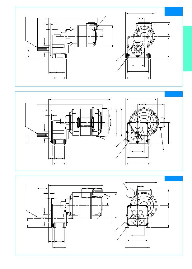
SD 38 MWS = 219
SD 29 MWS = 238
7
7.5
51
Ø 34
40
Ø 60
= 95 =
= 112 =
60
45
133
Dimensions in mm. Scale 1:4
NB: Unit drawn is SD 38 MIS
248
75
39.5
Ø 120
96.8
28.5
27.6
7
7.5
51
Ø 34
40
Ø 60
= 95 =
= 112 =
60
45
145
SD 18 MIS
Dimensions in mm. Scale 1:4
Optional shaft at motor speed (terminal box end only) see separate motor drawing for details (Page 9).
Optional shaft at motor speed (terminal box end only) 10mm dia.
33mm long.
Approx. weight: SD 18 MIS 7.42 Kg
Ø 120
96.8
28.5
27.6
SD13 MIS = 243
7
7.5
51
Ø 34
40
Ø 60
= 95 =
= 112 =
60
45
145
Ø 131
SD13 MIS (T.E.F.C.) = 281
94
SD 13 MIS
Dimensions in mm. Scale 1:4
Optional shaft at motor speed (lead end only) 10mm dia.
33mm long. Not applicable to T.E.F.C. units.
Approx. weight: SD 13 MIS 7.42 Kg
SD 38 MIS
SD 29 MIS
Approx. weight: SD 38 MIS 4.87 Kg
SD 29 MIS 5.64 Kg
4 holes tapped
M8
15mm deep.
4 holes tapped
M8
15mm deep.
4 holes on 48mm P.C.D.
Can be tapped
M5
11mm deep.
4 holes on 48mm P.C.D.
Can be tapped
M5
11mm deep.
Tapped 20mm conduit
or PG 13.5 on request.
14mm dia. h6.
Keyway 5mm
×
38mm long.
14mm dia. h6.
Keyway 5mm
×
38mm long.
4 holes tapped
M8
15mm deep.
4 holes on 48mm P.C.D.
Can be tapped
M5
11mm deep.
Tapped 20mm conduit
or PG 13.5 on request.
Electrolytic capacitor
when necessary.
14mm dia. h6.
Keyway 5mm
×
38mm long.
Leads out here 30cm
Optional terminal box tapped
20mm conduit or PG 13.5 on
request. Shown standard
position R.H.S. entry down.
(Standard on T.E.F.C. units).
35
Induction 1 & 3 Ph
Motor C
L
Motor C
L
Motor C
L