ALTB Top Mounted with
Bottom Support
·
Mixing, Dissolving, Solid Dispersion &
Suspension, Heat Transfer.
·
Radial, Flushed & Dry Running
Mechanical Seal Options.
·
High Sanitary Bearing & Impeller
Connection, Lantern Spacer, Bearing
Frame, Oil Trap Options.
ALB Bottom Mounted
·
Mixing, Dissolving, Solid Dispersion &
Suspension, Heat Transfer.
·
Cone Shaped and Fully Draining Tank
Flange.
·
Options Include; Fluid Trap, Single &
Double Mechanical Seals.
Patented Magnetic Mixer with levitating internal
impeller and external drive head for aseptic
applications. The magnetic coupling ensures the
impeller is fully levitated within a strong magnetic
field rather than resting on the guide bearing.
Eliminating axial contact and friction, allowing the
mixer to operate at any level and mix to the last
drop.
The Patented Rotary Jet Mixer provides fast and
effective mixing, positioned below the liquid level
in the tank. The mixer is driven by the flow of
recirculated liquid from an external loop. Rotation
in two axis provides 360 degree mixing. Additional
equipment in the recirculation loop allows powder/
gas dispersion and heating/cooling of the tank
media.
ALT Top Mounted
·
Mixing, Dissolving, Solid Dispersion &
Suspension, Heat Transfer.
·
Radial, Flushed and Dry Running
Mechanical Seal Options.
·
Modular Design Includes; Impeller
Connections, Lantern Spacer, Bearing
Frame, Oil Trap Options.
ALS Side Mounted
·
Maintaining a Homogeneous Media, Heat
Transfer.
·
Single & Double Mechanical Sealing
Options.
·
Options Include; Externally Detachable
Shaft, Lantern Spacer, Bearing Frame,
Oil Trap.
A
B
C
D
4301-0002
B
A
4301-0004
B
A
4301-0003
The Rotary Jet
Mixing technology
Impeller
Impeller magnets
Weld plate
Drive rotor magnets
Stationary bearing
Rotating bearing
Traditional Mixing technology
Round pumping Propeller mixing
eNSAFoIL eNeRGY SAVING AGITAToRS
MAGNeTIC MIXeR
MM UltraPure Magnetic Mixer
Iso-Mix Rotary Jet Mixer
ISo-MIX RoTARY JeT MIXeR
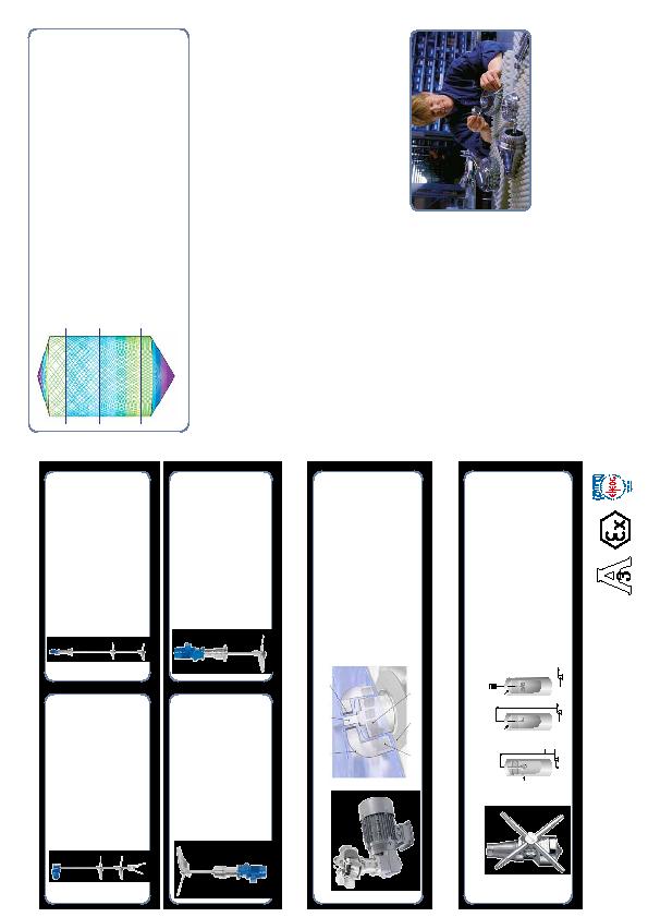
TRAX/CAS SIMULATIoN PRoGRAM
TRAX Simulation software allows inTank Technologies to validate and optimise the complete CIP process by
optimising the three key parameters for cleaning any tank.
·
Wetting intensity in l/m
2
.
·
Pattern mesh width in mm.
·
Transversal speed in m/sec.
·
Identifying and avoiding shadow areas.
·
Minimising cycle times and usage.
·
Maximise CIP coverage across the vessels internal surfaces.
·
Guaranteeing repeatable performance.
·
Identifying and avoiding shadow areas.
·
CAS selection and positioning tool enables inTank Technologies to:-
Ensure the optimum CIP head selection, quantity and positioning for each application.
Calculate required cleaning radius and dip pipe lengths.
Calculate the payback time.
SeRVICe AND SUPPoRT
SeRVICING
Our workshop facility is fully equipped to enable fast
and efficient servicing and repairs for all types of
cleaning head technology.
SPARe PARTS
Our parts department carry a full range of genuine
spare parts to support our full product range. Focused
on minimising customer downtime.
eNGINeeRING
Bespoke fabrication including adaptors, connections,
Dip Pipe assemblies, removable lances, spray ball manifolds developed specially to suit the customers
application. Enabling the installation of automatic CIP and Mixing technology into any process
application, which is our speciality.
oN-SITe SUPPoRT
·
Engineering support during commissioning.
·
On-site training for your maintenance team.
·
Site survey's enabling a full CIP and Mixing optimisation document to be written including pay back
calculations and an optimised CIP cycle programme.
TRAX Simulation Showing Wetting Intensity
2 cycles, 1.9 minutes
The simulation shows the cleaning pattern after 1.9 minutes.
4 cycles, 3.8 minutes
The cleaning pattern becomes progressively denser as the cleaning media covers
more and more of the tank's internal surfaces.
6 cycles, 5.7 minutes
After 6 cycles, wetting intensity has increased and coverage is almost total.
8 cycles, 7.8 minutes
After 8 cycles or 7.6 minutes, the entire internal surface area of the tank has been
impacted by the cleaning media and wetting intensity is at a maximum.
The above simulation is based on using the Toftejorg rotary jet head TG20G